WELDING POWER SOURCES
Napa.Ravi
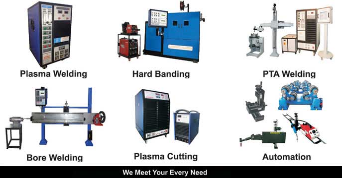
Arcraft Plasma Equipments (I) Pvt Ltd.
ABSTRACT
Introduction to welding power sources, various types, applications, useful definitions, relative advantages, disadvantages, what is an inverter in general, different power semiconductors used in inverters, different design topologies, Arcraft’s welding inverters and comparison of costs.
1. INTRODUCTION
- Welding is a process of joining two metals. To make a joint of two metals immense heat is required. This heat is created in the form of an electric arc. To create this arc a power source is required.
- Ever since the process of welding entered the engineering field there is continuous innovations in the field of welding power sources.
- The choice of a welding power source depends upon the process of welding.
- There are two types of welding power sources.
1.constant current power sources.
2.constant voltage power sources.
- A constant current power source is used in MMAW and TIG welding processes.
- MMAW stands for manual metal arc welding.
- TIG stands for tungsten inert gas welding.
- A constant voltage power source is used in MIG/MAG and SUBARC welding processes.
1.MIG stands for metal inert gas welding.
2.MAG stands for metal active gas welding.
3.SUBARC stands for submerged arc welding.
- Our discussion will cover power sources that are used in MMAW and TIG welding processes
- We may understand that welding can be carried out using
1.AC power source.
2.DC power source.
- The following are the types of welding power sources that can be differentiated based on value based parameters.
2. DIFFERENT TYPES OF WELDING POWER SOURCES.
2.A. AC power sources
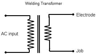
A1.Fixed current welding transformer.
A2.Variable current welding transformer (magnetic shunt type).
a) Moving iron
b) Moving coil
2.B. DC power sources.
B1.Transductor type welding power source (welding rectifier).
B2.Thyristorised welding rectifier.
B3.Chopper based welding power source.
B4.Inverter based welding power source.
3. SOME USEFUL DEFINITIONS
1. Power factor: It is the ratio between active power and the sum of active and reactive power. It should be noted that it is a vector sum not an algebraic sum.
2. Input KVA: It is the product of voltage applied and current drawn from the input power supply.
3. Input KVA single phase : Input voltage X Input current
4. Input KVA three phase : %3 X Voltage input X Input current
5. Input power :%3 X Voltage input X Input current X power factor
6. Output power : Output voltage X Output current
7. Output power : Input power X Efficiency
8. Open circuit voltage :This is the voltage available at the output terminals of welding power source when welding is not being carried out.
9. Load voltage: This is the voltage available at the output terminals of welding power source when welding is being carried out, given in Volts.
10. Welding current: This is the current drawn from the output of welding power source given in Amperes.
11. No load input current: This is the current drawn from the input power supply when welding is not being carried out.
12. deposition rate: It is the weight of material deposited in unit of time given in Kg/Hr or Kg/Min, under a given set of conditions. It is dependent of the power source also. It is reduced due to spatter and fumes. In a typical test it increases by about 15 to 20 % when welding inverters are used.
13. Melting/Burn off rate: It is the rate at which the electrode of specific size is melted by a set current and is expressed in cm/min. It increases rapidly as current is increased specifically for small diameter electrodes.
4. A DISCUSSION ON DIFFERENT TYPES
4.A1. Fixed current welding transformer.
Advantages:
1.Very low initial investment
2.Simple to use and service.
Disadvantages:
1.Very high no load current.
2. There is no control of current. Current is fixed, will also depends on the electrode and input voltage.
3.Very inefficient.
4.Very low power factor.
5.Due to 1 and 2 draws very large current from the electricity establishment. (see the table).
6.Due to 3 running cost is high.
7.Poor quality of weld.
8.Brute force of current.
9.Welding at low currents is not at all possible.
10.Bulky equipment, thus occupies large floor space.
11.Poor portability.
12.TIG / Argon welding not possible.
13.Welding of non- ferrous metals not possible.
14.Lower deposition rate and deposition efficiency.
4.A2. Variable current welding transformer (magnetic shunt type).
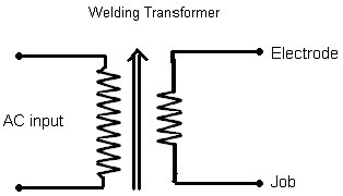
Moving core
or
Moving Iron |
Advantages:
1.Very low initial investment
2.Simple to use and service
Disadvantages:
1.Very high no load current.
2.Very inefficient.
3.Very low power factor.
4.Due to 1 and 2 draws very large current from the electricity establishment. (see the table).
5.Due to 3 running cost is high.
6.Poor quality of weld.
7.Better control of current compared to the previous type but not satisfactory.
8.Bulky equipment, thus occupies larger floor space.
9.TIG / Argon welding not possible.
10.Welding at low currents is not possible.
11.Poor deposition rate and efficiency
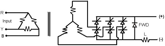
4.B2. Thyristorised welding rectifier.
Advantages:
1.Moderate initial investment
2.Simple to use.
3.Moderate skill required to service the equipment.
Disadvantages:
1.High no load current.
2.Efficiency is better than the earlier cases but not high.
3.Low power factor.
4.Due to 1 and 2 draws large current from the electricity establishment.
5.Due to 3 running cost is high.
6.Low speed of control.
7.Better quality of weld compared to the previous types.
8.Better control of current compared to previous types.
9.Bulky equipment, hence occupies large floor space.
10.Poor portability.
11.Averaage deposition rate and efficiency.
5. WHAT IS AN INVERTER?
An inverter used in the welding application functions as below.
- AC Line voltage is taken as the input to the welding equipment.
- It is suitably RFI/EMI filtered and rectified.
- This rectified voltage is filtered to make it pure DC.
- This Dc voltage is taken as the input to the switching device through a high frequency power transformer.
- As this switching frequency is very high the size of this transformer becomes very small compared to its counter parts.
- The transformer output is suitably stepped down.
- This stepped down AC voltage is again rectified using fast recovery diodes.
- This output is used for welding.
- Suitable controls and feedback techniques are used.
6. CHARACTERISTICS OF POWER SEMICONDUCTOR DEVICES USED IN INVERTERS
6a.Thyristers / SCRs (Silicon Controlled Rectifiers)
- Very large capacity devices are available, which are very rugged.
- Very low frequency of operation, which is well within the audio range.
- Gate drive is simple and efficient.
- Hence size and weight of the equipment is large.
- As the frequency of operation falls well in the audio range, welding is very noisy.
- As the commutation is forced, large and more number of components.
- Speed of current control is slow and hence a very low welding current is not possible.
- Large initial surge currents.
- High spatter and fumes. Poor quality of weld.
- Large internal heat due to large circulating current.
6b. BJTs (Bipolar Junction Transistors)
- All the above Drawbacks are eliminated, but It requires bulky and inefficient base drive, which is complicated and not suitable at high powers.
- High power transistors are extremely expensive.
- As the technology is advanced with IGBTs and MOSFETs there are no takers for these devices in welding application.
6c. MOSFETs(Metal Oxide Semiconductor Field Effect Transistors)
- In this device base is replaced by a gate.
Gate drive is simple and extremely efficient.
Very high switching speed, and hence transformer size becomes small.
Operation up to100KHz is easily possible.
- At larger duty cycles and higher power capacities size of transformer core has to be suitably selected to accommodate the adequate size of copper conductor.
- Large capacity devices are not popular due to their cost and availability.
- Hence used in low and medium capacity power sources.
6d. IGBTs (Insulated Gate Bipolar Transistors).
- It is a combination of BJT and MOSFET.
- Very simple and efficient gate drive.
- Large capacity devices are available at reasonable cost.
- Reduces assembly and servicing time.
Operation possible well above audio range and hence noise free operation.
- Only device available for large capacity power sources. Power loss is comparable to MOSFETs at low powers and lesser at medium and higher powers.
- And hence building block design concepts can be applied.
7. DESIGN TOPOLOGIES.
a. Resonant power sources.
b. PWM power source. (Pulse width Modulated)
7.a. Resonant power sources carry the disadvantage of large circulating current, bulky size due to commutating circuits. Hence they are less efficient. They offer less control bandwidth and hence wide variation of current is not possible. They produce less electromagnetic interference. Hence they are old generation for welding application. They are used at very high frequency typically 400KHz to 1000KHz in the field of communications, where EMI is a serious concern.
7.b. PWM power sources are the choice of the day as they offer large and fast control. EMI problem is suitably reduced using filters. They provide wide control of current typically from 3 to 400A, which is a very wide range. They provide a great opportunity to incorporate more features. The speed of correction is exceptionally advantageous to control current surges which is a necessity in TIG welding application. The PWM technique offers a smooth short circuit current control, a very good arc re-striking capability. And hence it is the latest and best choice for welding application.
7. HOW ARCRAFT’S EQUIPMENT IS BETTER THAN OTHERS?
1.Designed for wider input voltage fluctuations.
2.Designed for wider ambient temperature fluctuations.
3.Protected for under voltage, over voltage, single phasing and over temperature.
4.As many features are provided as required by the customer’s choice.
5.Ther is no surge of current, starts from the set value of current.
6.Very large number of models to choose from.
7.Tried and tested for quality.
8.Indegeniously designed and hence easy serviceability.
9.Trained manpower to provide service at your doorstep.
10.Very low down time as all the spares are easily available.
11.Due to high operating frequency of the inverter, very low ripple and due to this the welding current is smooth and stable. Excellent weld quality is produced.
12.Uniform weld beads, low spatter, and lesser fumes.
13.Very high deposition rate and efficiency.
14.Latest PWM technology using IGBTs.
COMPARISION
- Let us take 4mm arc welding electrode is being used
- It requires 160A welding current at approximately 24V
- Output power = 160 A X 24 V = 3840 W or 3.840 KW
- Input voltage is 230V AC in the case of single phase and 415V AC in the case of three phase input power supply. While comparing in an actual measurements the input voltage and output voltage has to accurately measured.
| Parameter
|
Welding Transformer
|
Welding Rectifier
|
Welding Inverter
|
| No load current |
4 to 5 A
|
4 to 5 A
|
0.3 to 0.5 A
|
| No load power factor
|
0.2
|
0.2
|
0.99
|
| No load power
|
400 to 500 W
|
400 to 500 W
|
50 to 100 W
|
| Output power
|
3.84KW
|
3.84KW
|
3.84KW
|
| Efficiency
|
0.6
|
0.6
|
0.9
|
| Input power
|
6.4 KW
|
6.4 KW
|
4.27 KW
|
| Input power factor
|
0.5 to 0.6
|
0.6
|
0.95
|
| Input KVA
|
12.8 to 10.66
at 230V,1ph
|
10.66
at 415V, 3 ph
|
4.5
at 415V, 3 ph
|
| Input current
|
55 A to 46 A
|
14.8 A
|
6.3 A
|
| Power consumption for 8 hrs a day
|
51.2 KWH
|
51.2 KWH
|
34.16 KWH
|
| Power consumption for 250 day of a year
|
12,800 KWH
|
12,800 KWH
|
8540 KWH
|
| Cost of electricity @ Rs 5 per KWH
|
Rs 64,000
|
Rs 64,000
|
Rs 42,700
|
| Excess in cost compared to Inverter
|
Rs 21,300
|
Rs 21,300
|
--
|
| Excess input current from supply
|
48 A
|
8.5 A
|
--
|
| Saving in running cost as above
|
--
|
--
|
Rs 21,300
|
| Saving in input current
|
--
|
--
|
8.5A to 48A
|
| Saving in installed capacity
|
--
|
--
|
6.1KVA to
11.0KVA
|
Therefore there is a saving of Rs 21,300 per anum if a machine is used for one year for 250 days @ 8 hrs a day, that is 2000Hrs per anum. We can calculate the same for the given number machines and hours used which will substantially reduce the cost burden
Also we can calculate the saving in the installed capacity, which will also saves on electricity bill.
This calculation is for 4mm electrode and for larger electrode sizes the savings will further increase.
|