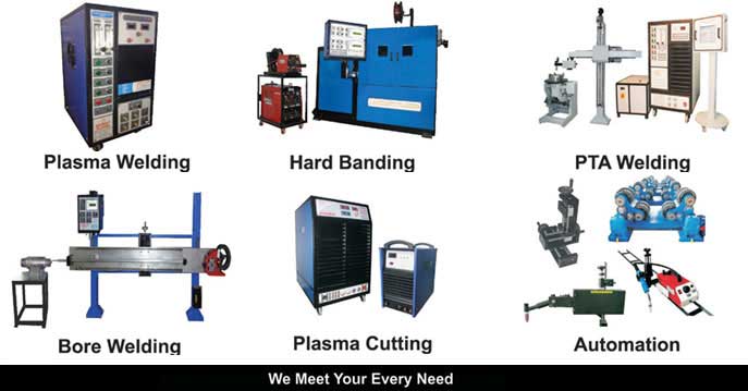
Micro TIG Welding Machines
EquipmentThe advent of inverter power sources has facilitated the design of very low current power sources which can reliably initiate and maintain a stable arc of 0.5 amps to an accuracy of 0.5%. Arcraft has taken a step further by introducing a power source which can maintain an arc length of 10mm also. A specially designed circuit enables the machine to work reliably using helium or argon as the shielding gas. A typical welding system usually consists of the following elements:
1.Welding power supply.
2.Weld controller.
3.Welding torch.
4.Gas connections and solenoid valves.
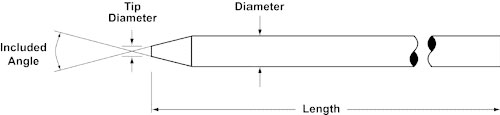
TechniquesTungsten Selection and preparation
To stabilize the arc it is necessary to use small diameter electrodes and the recommended electrode size for various current ranges are given in table 1.
Electrode diameter Current range
| Electrode diameter |
Current range |
Mm
in
|
A
|
| 0.250.010 |
0-2 |
| 0.50.020 |
3-8 |
| 1.00.040 |
8-20 |
Values are based on the use of thoriated , ceriated or lanthanated tungsten rods with argon as the shielding gasA.Electrode Diameter - The welding equipment supplier's recommendations and the American Welding Society recommendations are the best place to start with this variable. Keep in mind that as you increase the diameter of the electrode you are able to handle more amperage. For a given amperage, larger diameter electrodes are more difficult to start than smaller ones, but they will probably erode less rapidly. If you use too large an electrode for your amperage level, you are likely to experience arc instability.
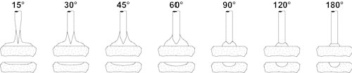
B.Electrode Taper - This is usually called out in degrees of included angle (usually anywhere between 14 degrees and 60 degrees). Below is a summary chart that illustrates how different tapers offer different arc shapes and features:
| Sharper Electrodes |
Blunter Electrodes |
| Easy arc starting |
Usually harder to start the arc |
| Handle less amperage |
Handle more amperage |
| Wider arc shape |
Narrower arc shape |
| Good arc stability |
Potential for more arc wander |
| Less weld penetration |
Better weld penetration |
| Shorter electrode life |
Longer electrode life |
Arc Shape and Fusion Zone Profile as a Function of Electrode Included Angle The fusion zone profile will depend on: 1.Electrode tip diameter (flat)
2.Arc Gap
3.Material to be welded
4.Shield gas used
C.Electrode Tip Diameter - Grinding an electrode to a point is sometimes desirable for certain applications, especially where arc starting is difficult or short duration welds on small parts are performed. However in most cases it is best for a welder to leave a flat spot or tip diameter at the end of electrode. This reduces erosion at the thin part of a point and reduces the concern that the tip may fall into the weld. Larger and smaller tip diameters offer the following trade-offs:
| Smaller Tip |
Larger Tip |
| Easier arc starting |
Usually harder to start the arc |
| Potential for more arc wander |
Good arc stability |
| Less weld penetration |
More weld penetration |
| Shorter electrode life |
More electrode life |
Grinding
Proper Tungsten preparation is a key variable in the quality of your welding. Even the best welding equipment can not overcome the effects of a badly prepared and contaminated electrode. Properly ground electrodes reduce or eliminate arc wander, splitting, shedding, welding quality inconsistencies and scrap of expensive parts.
Always use a dedicated Tungsten grinder. Grinding electrodes on regular shop equipment or grinding other materials on tungsten grinders leads to contamination of the electrode and reduced welding performance. In addition, dedicated grinder allow for geometry measurement for testing and for maintaining consistency of preparation according to established procedures.
Grind longitudinally and concentrically so that the lines on the ground surface move in the same direction as the electrode and the electrode has no flat spots. Grinding crosswise causes arc wander and risk inclusions in some applications.
Since tungsten is a very hard material, grinding wheels should be made of diamond or borazon.
Electrodes should be cut using a cutting wheel where possible. Notching and breaking or using pliers to snap electrodes can cause splintering in the electrode that is difficult to see and can create a weld defect. Selection - No single material is the right choice for every application. In the past, mostwelders used 2% Thoriated Tungsten for most DC welding applications. However, because this material is slightly radioactive and ingestion of the dust during grinding represents a health hazard, many welders have looked to other alternatives. Non-radioactive 2% Ceriated Tungsten has proven itself to be very good in low amperage welding and is commonly used by orbital welders. The new non-radioactive 1½% Lanthanated Tungsten electrode is an excellent substitute for 2% Thoriated Tungsten in almost every application. In addition, independent, controlled tests have shown that it actually offers better arc starting and longer life.Shield gas
The shield gases used with tungsten electrodes must only be oxygen-free gases and gas mixtures. Even a very small content of oxygen leads to surface oxidation (recognized by a blue colour on the electrode tip) . The flow of shield gas should continue after the arc is extinguished until the electrode has cooled (T < 250° C). Electrode protrusion
The end of the electrode protruding from the nozzle should be as short as possible in order to guarantee optimum flow of shield gas.
Ventilation
To ensure the optimum flow of shield gas during welding, it is essential to avoid draughts. Of course, this does not mean that the extraction of welding fumes can be neglected in any way.
Immersion of electrode tip in weld pool
It is essential to prevent the immersion of the electrode tip into the molten weld pool, as this impairs the arc Electrode Diameter Welding parameters
For welding in many precision or high-purity applications, a specification may already be written that outlines the recommended welding parameters, including the base material; part diameter(s); weld joint and part fit-up requirements; shield gas type and purity; arc length; and tungsten electrode material, tip geometry, and surface condition.
Some welding equipment suppliers offer a series of precalculated weld programs for a variety of part diameters, materials, and thicknesses. Welders should always follow an equipment supplier's suggested procedures first because the suppliers usually have performed a significant amount of qualifying and troubleshooting work. Of course, equipment suppliers can not possible have welding procedures for every welding application, This article is intended as a guideline for those GTAW applications in which no specification exists and the engineer responsible for the welding must create the welding setup and derive the welding parameters.
The rules of thumb noted here are general guidelines only and will not apply to every welding application and mix of parameters chosen. Although the welding parameters often are chosen and changed according to the specific needs of the application, some industry standards have been developed as starting points. Experimentation and experience will determine the final weld parameters. The addition of wire to the process creates many additional parameters. This article focuses on fusion welding only.Arc Length
The arc length (sometimes called the arc gap) is the distance from the electrode tip to the part to be welded. This setting is dependent on weld current, arc stability, and part concentricity/ovality. The welding engineer's objective is to keep the electrode at a constant distance from the part surface with a sufficient gap to avoid stubbing out. As a rule of thumb, an arc length of 0.10 inch acts as a base. Half the weld penetration required , expressed in thousandths of an inch, is added to the base measurement to give the arc length for a given amperage. Thus, if the part material thickness is 0.030 inch, the a good starting arc length would be 0.010 inch + 0.015 inch = 0.025 inch. For a material thickness/ penetration of 0.154 inch, a good starting arc length would be 0.010 inch + 0.072 inch = 0.082 inch. Weld Speed
The weld speed, which is the speed of travel of the torch over the part or the part under the torch, is dependent on the flow rate of the material to be welded and the material thickness. The objective is to weld as quickly as possible while still yielding a quality output. Weld speed is a predominant factor in defining the production output of a welding system. Orbital welding equipment weld speeds usually are 4 to 10 inches per minute (IPM), lathe welding speeds may be 5 to 60 IPM, and tube mill welding speeds can vary from 3 IPM to 60 feet per minute (FPM) .As a starting point for parts rotated under a welding torch, the tungsten surface speed should be 10 to 20 IPM, with the faster welding speeds used for thinner-wall materials and the slower speeds used for heavy-wall thicknesses.
Welding Current
The welding current corresponds to the amount of heat applied to the part to effect the weld, and it depends on the material to be welded, material thickness, welding speed, and shield gas. The objective is the achieve defect-free welds with the required penetration. The welder should start by using 1 amp of welding current for every 0.001 inch of material thickness and for each 10-IPM weld speed increment if the material is stainless steel. Thus, for a 0.030 inch material thickness, the average weld current would be 30 amps in the first level with average weld speeds . To compensate for heat buildup in circular parts during welding, a downslope at the end of the weld or multiple levels of weld current can be used. If the weld current used to initially penetrate the parts were held at the same level for the complete weld, the weld penetration would increase as the weld progressed around the part potentially producing too much penetration
The number of levels of welding current needed depend greatly on the welding application and the associated welding speed.Pulsing
Arc pulsing involves using the welding power supply to alternate the weld current rapidly from a high (peak current) to a low (background current) value. This creates a seam of overlapping spot welds.This technique reduces the overall heat input to the base material and also can allow for increases in weld speed. Arc pulsing brings many benefits to the welding procedure, often improving weld quality and repeatability. In some cases, materials and weld joints with poor fit-up that are difficult to weld successfully with a nonpulsed arc can be welded easily with a pulsed arc technique. The results are improved weld quality and increased output. Arc pulsing involves four welding parameters: peak current, background current, pulse width (pulse duty cycle or on-time), and pulse frequency. Many welders arrive at the same welding result using somewhat different welding parameters. The primary objective is to use the benefits of weld pulsation to improve weld quality and output. Peak-to-background current ratios. The peak-to-background current ratios basically provide a means for the welding current to pulse form one level to another. Industry usage generally varies from 2:1 to 5:1 ratios. A good starting point is to use a 3:1 ratio, make the required weld, and test other parameters to see if any benefit can be gained. Pulse frequency. The pulse frequency depends on the required spot overlap. A good starting parameter is to try to achieve 75 percent spot overlap. The pulse rate for thin-material parts welded at slow speeds often is equal to the weld speed in IPM (for example, 5 IPM = 5 pulses per second).
Pulse width
The pulse width--the percentage of time spent on the peak current--is dependent on the heat sensitivity of the material and the maximum available current from the power supply. Material with higher heat sensitivity may require a lower pulse width percentage on the peak current. Standard pulse width are often 20 to 50 percent. A good starting point is to set a pulse width of 35 percent.
Backing system
When welding high integrity components, a shielding gas is used to protect the underside of the weld pool and weld bead from oxidation. To reduce the amount of gas consumed, a localised gas shroud for sheet, dams or plugs for tubular components is used. As little as 5% air can result in a poor weld bead profile and may reduce corrosion resistance in materials like stainless steel. With gas backing systems in pipe welding, pre-weld purge time depends on the diameter and length of the pipe. The flow rate/purge time is set to ensure at least five volume changes before welding.
Stick on tapes and ceramic backing bars are also used to protect and support the weld bead. In manual stainless steel welding, a flux-cored wire instead of a solid wire can be used in the root run. This protects the underbead from oxidation without the need for gas backing.
Insert
A pre-placed insert can be used to improve the uniformity of the root penetration. Its main use is to prevent suck-back in an autogenous weld, especially in the overhead position. The use of an insert does not make welding any easier and skill is still required to avoid problems of incomplete root fusion and uneven root penetration.
Protective equipment
A slightly darker glass should be used in the head or hand shield than that used for MMA welding.
Recommended shade number of filter for TIG welding:
| Shade number |
Welding current A |
| 9 |
less than 20 |
| 10 |
20 to 40 |
| 11 |
40 to 100 |
| 12 |
100 to 175 |
| 13 |
175 to 250 |
| 14 |
250 to 400 |
Weld Preparations
Decisive for the success of a weld joint are the following factors
Parent metal
Cleanliness of the plate edges
Torch Position
Parameter setting ( energy input/welding speed)
Weld shape
Heat dissipation from the weld joint. Applications
Welding of bellows , transducers , seals, thermocouples , sensors , tubes , diaphragms , batteries , medical implants, tube to flange , foils and many others.
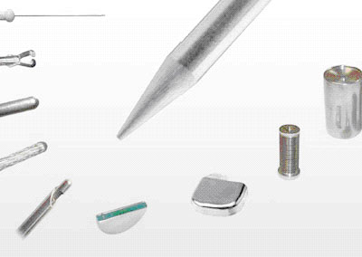
Materials which can be welded
Stainless, heat-resistant, and other steels; titanium; Inconel; Kovar; zircalloy; tantalum; copper; brass; gold; and silver.Summary of the Fundamentals of Precision Arc Welding
In arc welding processes a multitude of welding parameters exist that can affect the size, shape, and quality of the weld. Many weld parameters, or variables, exist and each can be discussed at length. It is imperative however, that the engineer responsible for welding have, at minimum, an understanding of how to choose and modify the basic parameters for simple weld applications.
Listed below are the fundamental elements to understand.
1.The physics of welding, arc starting, arc voltage, weld current, and heat input (watt-secs).
2.Design of the weld joint, joint fit-up requirements, and heat balance considerations.
3.Tooling design: materials and geometry.
4.Rules of thumb for choosing the correct weld current. How to recognize insufficient or excess weld current.
5.The six main benefits of arc pulsing. How to choose the pulsation rates empirically or from pre-calculation.
6.The effect of weld speed. What happens when the weld speed is too fast or too slow?
7.Arc length--how to choose the correct arc length. What happens when the arc length is too long or too short?
8.Welding electrode--the effect of electrode material and geometry on the weld shape.Electrode materials available. Grinding requirements.
9.Shield gases--how to choose the shield gas and gas purity grade. Gas types and mixtures, argon, helium, argon/hydrogen. The effect of hydrogen on the arc and weld quality. Gas lens requirements.
Prepared by welding applications cell at ARCRAFT.
|